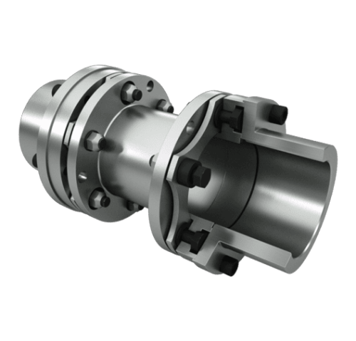
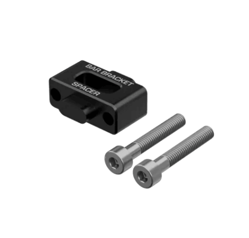
Custom Drone Landing Gear and Mounts Featured Image
  • Materials
    7075-T6 and titanium
  • Gear Parts
    Mounts, clamps, hinges
  • Inspection
    CMM report on request
  • Engineering
    DFM review, NDA on request

Precision-Machined Drone Landing Gear Parts

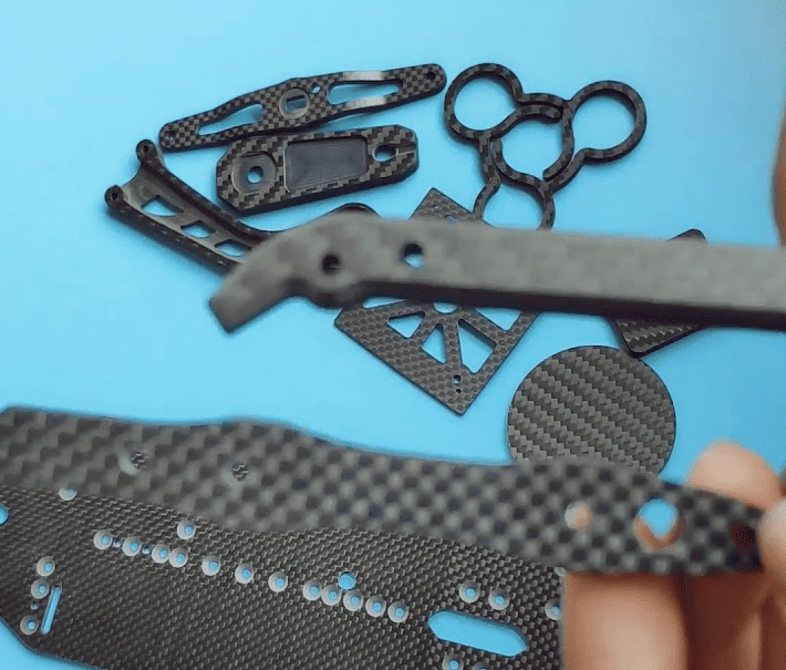
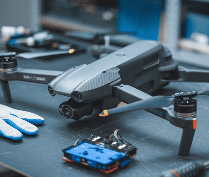
We machine landing gear parts to your drawing: the frame mounts, tube clamps, hinges and foot fittings that carry an industrial UAV from the airframe to the ground. Our customers are UAV OEMs and integrators building heavy-lift, inspection, delivery and agricultural aircraft, with gear that fits their own frame rather than a retail kit.

Every part is made from your CAD and inspected on CMM, with inspection documents on request, from the first prototype set to repeat production batches. Landing gear mounts belong to our structural UAV components family.

Request a Quote
Product Intro Image

Drone landing gear parts we machine

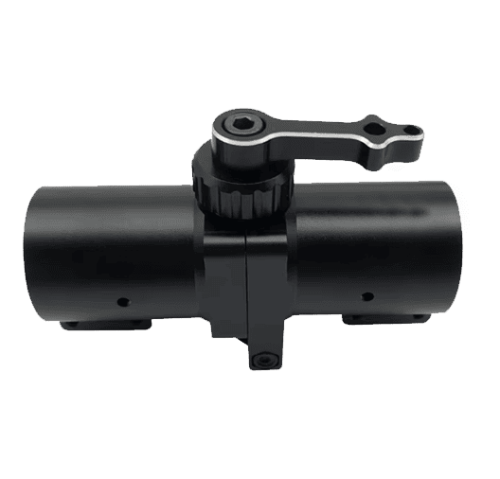
Frame mounts and brackets

The interface between the center plate or fuselage and the gear legs. A mount spreads landing loads into the frame through several fasteners and a flat seating face, so bolt pattern and face flatness are machined to the frame datums. It pairs with our drone center plates.

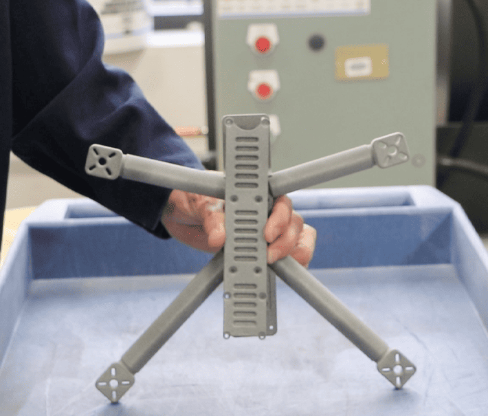
Drone frame arms
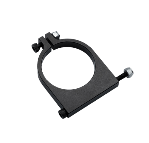
Tube clamps and T-connectors

Clamps and T-pieces for legs and skids in aluminum tube, or carbon tubes or plates with machined aluminum fittings. Tube OD is set by your design, commonly 16–30 mm on industrial multirotors. Split clamps, pinch clamps and bonded sockets are machined to the bore and clamp length on your drawing.

Request a quote
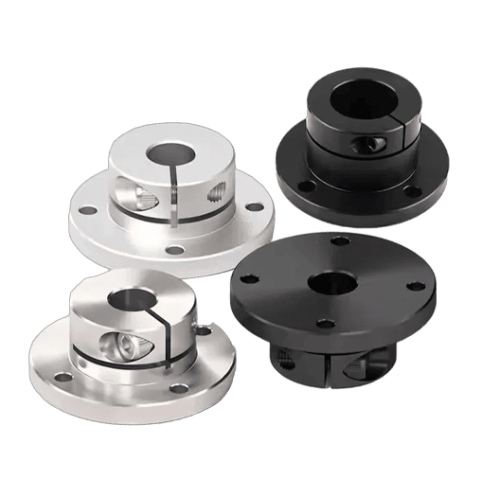
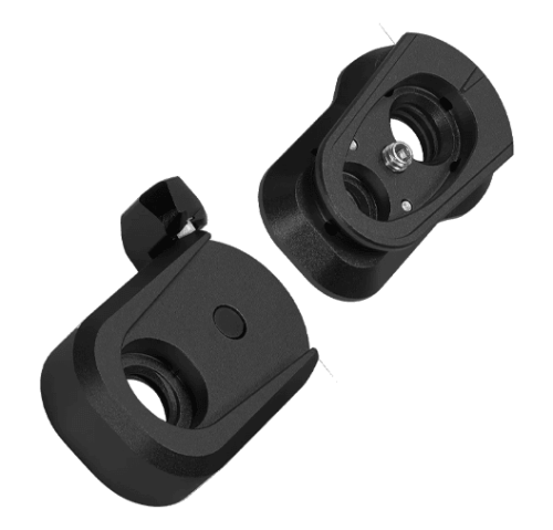
Folding and retractable hinges

Pivot blocks, locking pins, detents and servo or actuator brackets for gear that folds for transport or retracts in flight to clear the camera’s field of view.

Request a quote
Skid end caps and foot inserts

End caps and threaded inserts, machined to your drawing, that take rubber pads, floats or ground sensors at the bottom of each leg or skid of an industrial multirotor.

Request a quote

Manufacturing Process & Quality

  • Material Selection Featured Image
  • CNC Machining Featured Image
  • Deburring & Cleaning Featured Image
  • Surface Finish Featured Image
  • Final Inspection Featured Image
Material Selection
Alloy and temper taken from your drawing: 7075-T6 or 6061-T6 aluminum first, Ti-6Al-4V or stainless steel where high-load pins, pivots and shafts ask for it.
CNC Machining
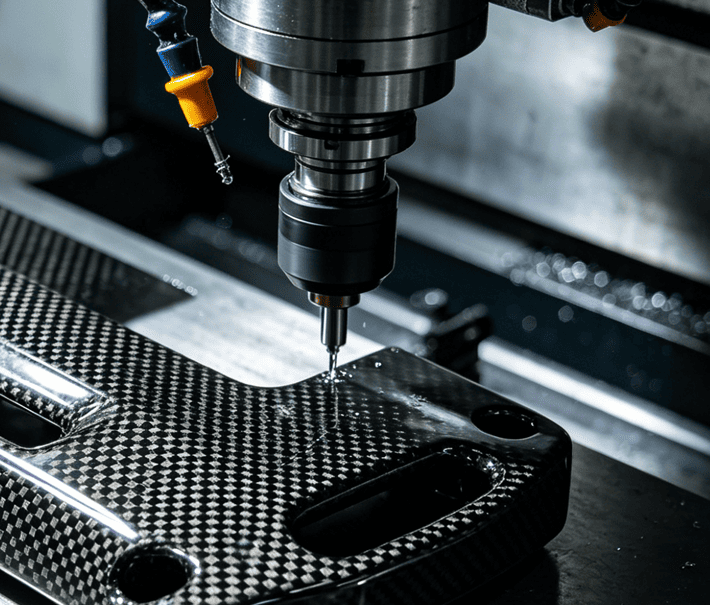
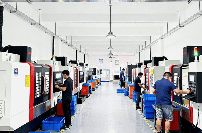
CNC machining to the approved drawing revision, with the same program and fixtures on every repeat order so bores, hole patterns and bolt patterns repeat from prototype to batch.
Deburring & Cleaning
Edges broken and clamp entry edges rounded as the drawing calls out, then parts cleaned so bores, threads and mating faces are free of chips and oil before finishing.
Surface Finish
Hard anodizing, black anodizing, chem film, electroless nickel or laser marking, applied as specified on the drawing, with masking where the drawing requires bare metal.
Final Inspection
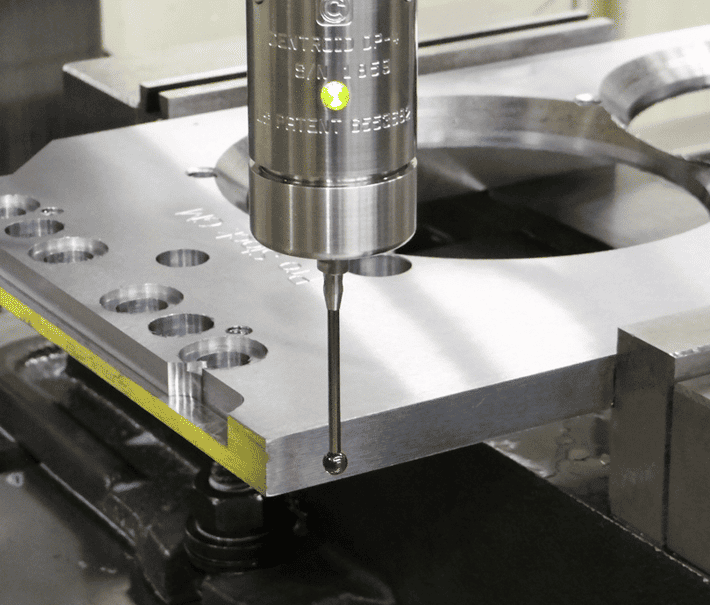
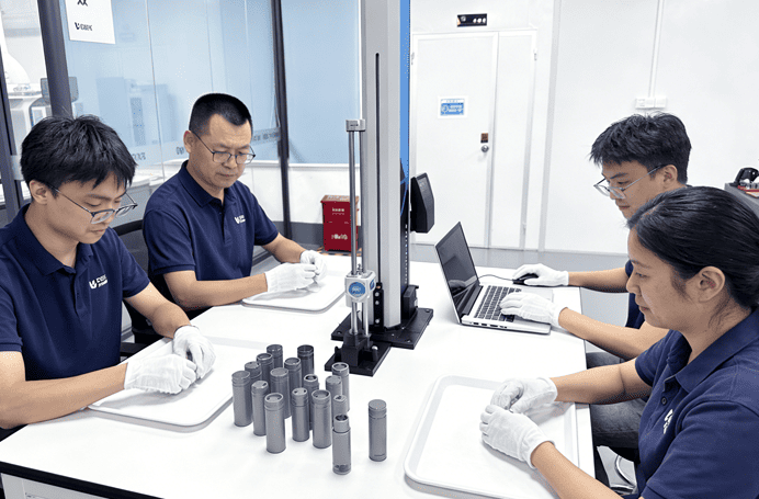
Bores, hole patterns and mounting-face flatness checked on CMM against your datums; the inspection plan is kept for repeat batches, with CMM reports on request.

Landing gear mounts to your drawing

We keep revision control on each drawing, so a repeat order is machined to the approved revision with the same program, fixtures and inspection plan, as matched sets per aircraft.

Tube size and clamp Icon
Tube size and clamp
Hinge position Icon
Hinge position
Leg length Icon
Leg length
Hard anodizing Icon
Hard anodizing
Request a Quote
  • Tube size and clamp Featured Image
  • Hinge position Featured Image
  • Leg length Featured Image
  • Hard anodizing Featured Image

Design points for heavy-lift drone landing gear

Load path

Landing loads travel from the foot through the leg, the clamp and the frame mount into the airframe. Each joint should carry load in bearing or shear, not by friction alone.

Landing impact

Gear for a heavy-lift aircraft is sized on the maximum take-off weight (MTOW) and the hardest landing the program accepts. Load cases and margins come from your engineering team; we machine to the result. See heavy-lift drone design.

Tube clamping

The main pain point. Too tight a bore or too short a clamp crushes a tube leg; too loose and the leg rotates. Clamp length, bore tolerance, split versus pinch design and rounded entry edges prevent this.

Vibration

Gear legs can resonate with motor and propeller frequencies. Damping elements at the frame mount help; see vibration damping mounts.

Folding and payload clearance

Hinges and quick-release locks let large frames fit a case without tools. Gear height and leg spacing must clear gimbals and sensors slung under the airframe.

Corrosion

Spraying aircraft see fertilizers and crop chemicals, and maritime work brings salt spray. Finish choice matters for agricultural UAV parts.
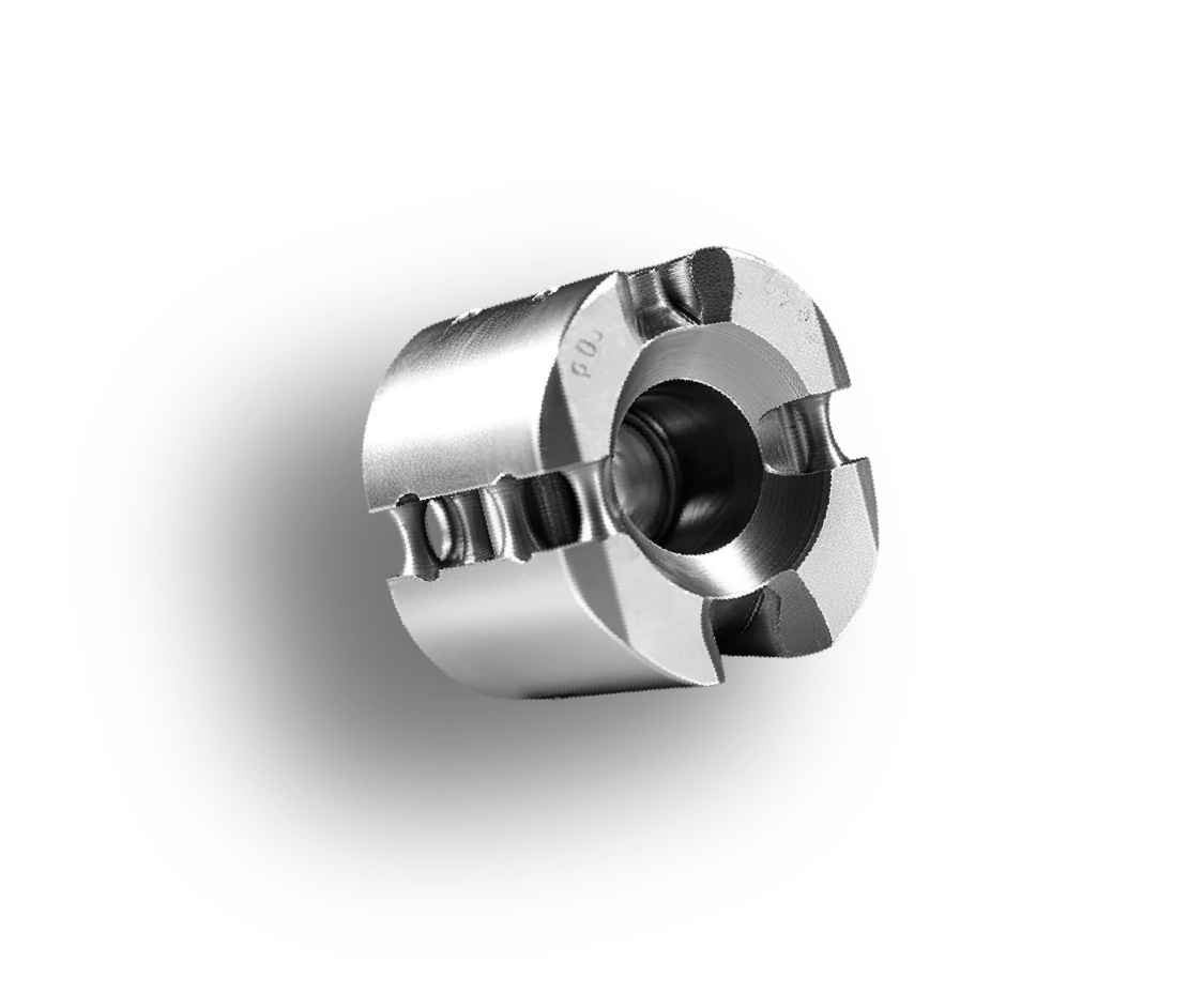
Technical Specs

Specs Image
Parameter Specification
Materials 7075-T6 and 6061-T6 aluminum; Ti-6Al-4V (Grade 5); stainless steel; Delrin or nylon
Legs and skids Aluminum tubes, or carbon tubes or plates with machined aluminum fittings
Tube sizes Tube OD set by your design, commonly 16–30 mm on industrial multirotors
Finishes Hard anodizing (MIL-A-8625 Type III); chem film (MIL-DTL-5541); electroless nickel (pins)
Color coding Black or color-coded anodizing (MIL-A-8625 Type II) to tell front and rear gear apart
Tolerances ISO fits on pins (e.g. H7 bore, g6 pin); ISO 2768 general; GD&T to ASME Y14.5
Inspection Bores, hole patterns and face flatness on CMM to your datums; same plan on repeats
Documentation CMM report on request; laser marking of part IDs and revisions
Production Prototype to repeat batches, revision-controlled, matched sets per aircraft

Frequently Asked Questions

Answers on drone landing gear parts, materials, tube clamps, finishes and order quantities for industrial UAV programs.

Send your drawing for a DFM review

Upload your CAD and 2D drawing. An engineer reviews it before machining, we sign NDAs on request, and repeat batches are built to the same inspection plan.

Upload your CAD
Do you sell complete drone landing gear kits?
No. We machine the landing gear parts and mounts to your drawing; legs can be your tubes or machined parts.
Which material is best for heavy-lift landing gear mounts?
7075-T6 aluminum is the usual choice for clamps and brackets; titanium is used for high-load pins and hinges.
Can you make folding or retractable landing gear parts?
Yes, we machine hinge blocks, locking pins and servo brackets to your design.
How do you avoid damaging tube legs with clamps?
By controlling the bore tolerance and clamp length and rounding edges, as specified in your drawing; we can suggest DFM changes.
What is the minimum order quantity?
There is no minimum order quantity: from one prototype to production runs.
Which finish should I choose for agricultural spraying drones?
Hard anodizing or anodizing with sealing improves corrosion and wear resistance; confirm the choice against your chemical exposure.
Will the surface treatment interfere with part dimensions?
No. The thickness of hard anodizing or plating is allowed for before machining, so tube bores and pin fits are within tolerance once the finish is applied; masking is specified where the drawing requires bare metal.
How do you ensure the landing gear mounts won't fail under stress?
At the DFM review we look for sharp internal corners that act as stress risers and suggest fillets or radii; bores and clamp lengths are checked against your tube and pin sizes, and the critical features are inspected on CMM.