DFM for Drones: 10 Tips to Lower CNC Costs Without Sacrificing Quality
Kim
Kim oversees complex DFM reviews and process planning. He specializes in tight-tolerance machining for drone gimbals, motor mounts, and propulsion systems, ensuring flight-critical precision and structural integrity.
CNC machining, in some ways, determines how drone components fulfill their functions and perform in real-world conditions. From my experience, I’ve witnessed how even the smallest decisions that may not look significant can increase cost and machining time when manufacturability was not carefully considered.
For me, this is the reason why DFM for drones guides my choices. It gives me control over costs without sacrificing quality, weight balance, precision, and reliability demands.
What is DFM?
Design for Manufacturability, or DFM, is a method used in designing parts while considering manufacturing constraints during the early stages of project planning. In my drone projects, I apply DFM by selecting materials based on machinability and functional demands. Utilizing DFM ahead eliminates the possibilities of rework, reduces production risks and material waste, and maintains consistent performance without driving the costs higher than expected.
10 Tips to Lower CNC Costs Without Sacrificing Quality
1. Avoid Over-Specifying Tolerances
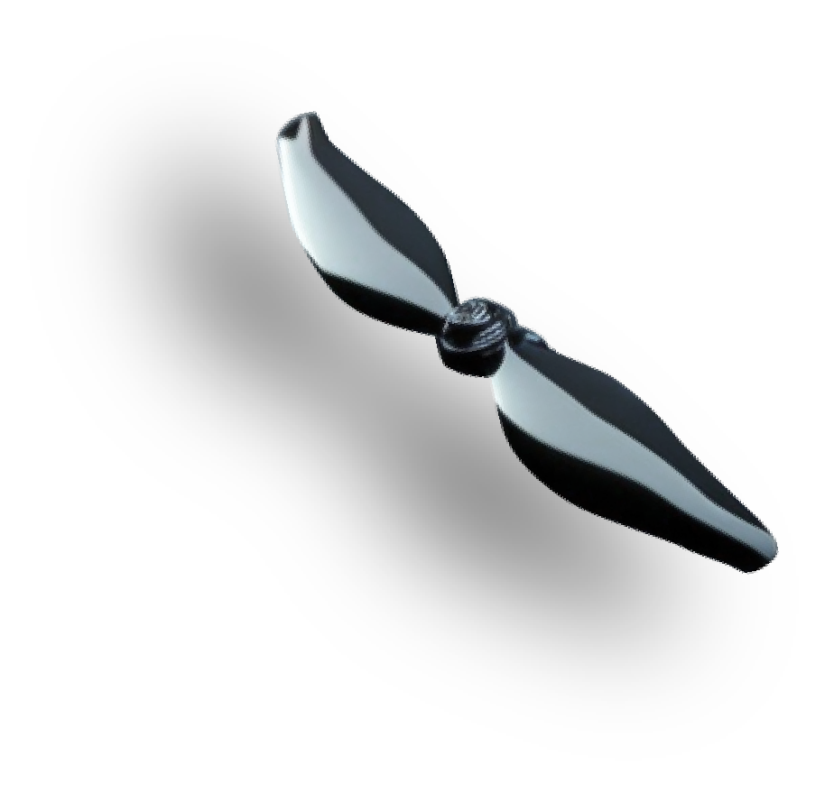
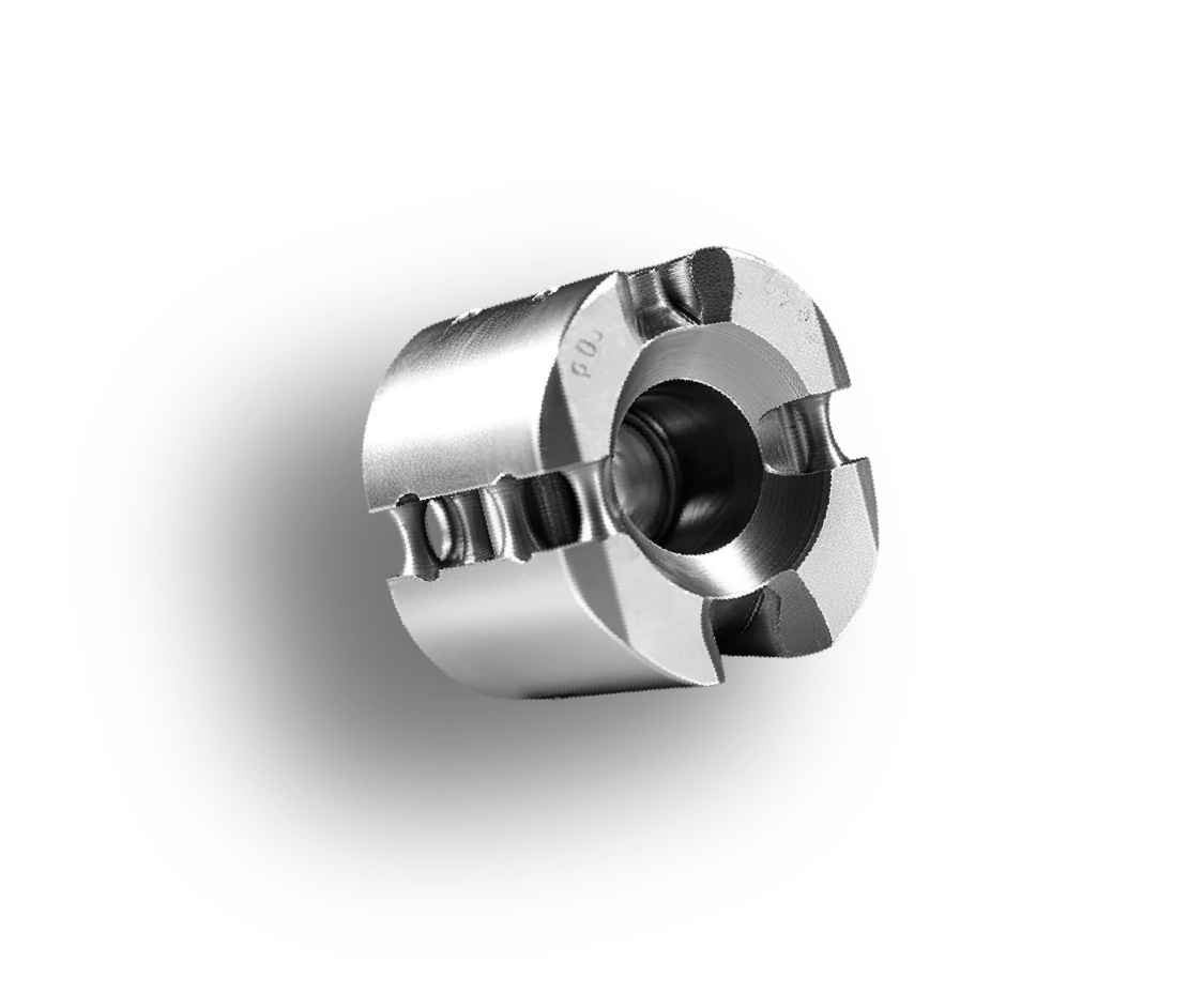
Drone parts don’t need very tight tolerances to precisely perform their function. For me, one good example is flight-critical components like propeller hubs or motor mounts. Yes, they need precision, but other structural parts can use a bit more leeway.
The tendency is to slow down machining when pushing ±0.005 mm. It increases scrap risk and inspection time, so I make sure to be strict on tight tolerances only on places that need it most.
2. Design with Standard Tool Sizes
I am always concerned about the cutter sizes on hand. Which is why I always check while planning my drone components. It saves me from unnecessary tool changes when I use standard diameters, mainly 3 mm, 6 mm, or 12 mm, which keeps CAM programming simple.
As much as I can, I also avoid slot widths or radii that would eventually need custom tools. Whenever I do this, it saves me hours of machining. Small but significant features like internal support, mounting holes, and ribs are components that give strength to the drone without adding extra weight.
3. Maintain Uniform Wall Thickness
For parts like carbon steel brackets and aluminum frames, the wall thickness needs to be consistent. With that, I keep my walls around 2–4 mm for steel, and 1–3 mm for aluminum. But I still consider the part’s load, so bending or warping during machining and vibration could be prevented.
I also avoid sharp internal corners and deep pockets because these extra challenging designs can cause stress buildup that affects stability while the drone is in flight.
4. Optimize Hole Depth-to-Diameter Ratios
I keep holes no deeper than 8-10 times their diameter for components like battery brackets or standoffs and motor mounts. For instance, 32-40mm at most for a 4 mm mounting hole. Going deeper than that will only require special drilling cycles, increase tool wear, and even slow production.
When I keep it within range, I get accurate holes while maintaining structural integrity. It also reduces breakage risks and makes the drone stable during flight.
5. Minimize Undercuts and Internal Sharp Corners
Custom tooling and sometimes, even EDM machining, are needed for undercuts in drone parts, which is why I try to avoid them whenever I can. Since I cannot skip internal corners, I am strict about sticking to the minimum radius that is just equal to the cutter diameter.
When I do this, the tools reduce stress concentration because they move smoothly, and that achieves precise shapes that meet the drones’ demands.
6. Reduce Setup Changes
Setup time and alignment issues add up each time parts need to be reoriented on the machine. So I always consider components that have features that can be machined in a single setup. In case I need to deal with multiple face features, that’s where multi-axis machining steps in. But this only happens when it’s truly necessary.
7. Choose Machinable Materials
Focusing on materials that can balance ease of machining, weight, and strength is important when working with CNC-machined parts. It’s undeniable that aluminum 6061 is the best pick for brackets and frames because it cuts quickly, handles tolerances while keeping the drone lightweight. In this case, I avoid inconel and titanium unless the drone needs some components to be extra hard and stronger for temperature resistance.
Hard materials tend to slow operations and wear tools faster, hence adding more costs.
8. Consolidate Features Where Possible
Even a tiny extra slot or hole consumes more time in CNC. That’s why whenever possible, I look for ways to merge adjacent holes, remove features that are not necessary, and simplify patterns.
One good example is trimming decorative cuts that are not necessary because it cuts machining time while keeping drone integrity.
9. Plan for Surface Finish Early
Before I decide on what specific surface finish I need for my drone parts, I always consider how electropolishing and anodizing affect dimensions. Because surface finishes can change mating surfaces and fits.
Considering this ahead of time gives me a chance to set flatness and tolerances that apply to the finish.
10. Annotate Drawings Clearly and Completely
The last consideration is to make sure that 2D drawing designs include important details. I should be aware of the material, tolerances, specs, and surface finish. If anything is not clearly detailed, it may cause future miscommunication on the CNC floor.
In terms of 3D models, I thoroughly check if everything matches. Clear and precise annotations reduce errors, save time, and help parts come out perfectly as designed.
Conclusion
DFM for drones has helped me in many ways to reduce costs while keeping quality, reliability, and precision. These guidelines, from tolerances to features, contribute to the smooth production of accurate and high-performing drones.
If you are strict about quality but at the same time, you also don’t want to overspend, DroneCNCParts can help. Our expertise can convert design into precisely machined components that are not only easy to assemble but also strict about meeting drone flight standards.